REAR WHEEL ALIGNMENT
Specification (Unloaded Condition)| Item |
Specification |
||
| Total toe-in |
Tire [Tolerance ±4 {0.2}] |
(mm ) |
3.0 {0.12} |
| Rim inner [Tolerance ±2.8 {0.11}] |
Vehicle equipped with 16 inch wheel: 2.0 {0.079} Vehicle equipped with 17 inch wheel: 2.1 {0.083} |
||
| degree |
0°17′±20′ |
||
| Camber [Tolerance ±1° |
Vehicle height: From the end of the rear fender to the center of the wheel (mm ) |
350—358 {13.8—14.0} |
-1°23′ |
| 359—367 {14.2—14.4} |
-1°09′ |
||
| 368—376 {14.5—14.8} |
-0°57′ |
||
| 377—385 {14.9—15.1} |
-0°46′ |
||
| 386—394 {15.2—15.5} |
-0°37′ |
||
NOTE:
Unloaded condition: Fuel tank is full. Engine coolant and engine oil are at specified level. Jack and tools are in designated position.
Difference between the left and right camber angle must be within 1°.
Camber Adjustment
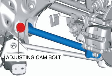
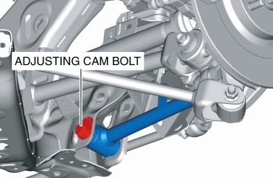
1. Loosen the installation nut of the lower link adjusting cam bolt.
2. Rotate the adjusting cam bolt in either direction to adjust the camber. Specification
Vehicle height*
Camber
350—358 {13.8—14.0}
-1°23′±1°
359—367 {14.2—14.4}
-1°09′±1°
368—376 {14.5—14.8}
-0°57′±1°
377—385 {14.9—15.1}
-0°46′±1°
386—394 {15.2—15.5}
-0°37′±1°
*: Vehicle height: From the end of the rear fender to the center of the wheel (mm )
Left wheel
Right wheel
Positive direction
Clockwise
Counterclockwise
Negative direction
Counterclockwise
Clockwise
NOTE:
Lower link adjusting cam bolt adjustment table
Refer to the following figure to adjust the angle of the adjusting cam bolts in single increments.
Scale
Link movement (mm )
Camber change amount (angle)
1
1.8 mm {0.071 in}
-0°35′
2
3.5 mm {0.14 in}
-1°08′
3
4.9 mm {0.19 in}
-1°36′
4
6.1 mm {0.24 in}
-1°58′
5
6.8 mm {0.27 in}
-2°11′
6
7.0 mm {0.28 in}
-2°16′
3. Tighten the nut.Tightening torque
85—103 N·m {8.7—10 kgf·m, 63—75 ft·lbf}
Total Toe-in Adjustment
1. Loosen the installation nut of the lower lateral link adjusting cam bolt.
2. Rotate the adjusting cam bolt in either direction to adjust the toe-in.Specification
3.0±4 mm {0.12±0.2 in} (0°17′±20′)
Left wheel
Right wheel
Toe-in direction
Counterclockwise
Clockwise
Toe-out direction
Clockwise
Counterclockwise
NOTE:
Lower lateral link adjusting cam bolt adjustment table
Refer to the following figure to adjust the angle of the adjusting cam bolts in single increments.
Scale
Link movement (mm )
Toe change amount (angle)
1
1.8 mm {0.071 in}
0°30′
2
3.5 mm {0.14 in}
0°57′
3
4.9 mm {0.19 in}
1°21′
4
6.1 mm {0.24 in}
1°39′
5
6.8 mm {0.27 in}
1°50′
6
7.0 mm {0.28 in}
1°54′
3. Tighten the nut.< Previous Next >Tightening torque
85—103 N·m {8.7—10 kgf·m, 63—75 ft·lbf}

