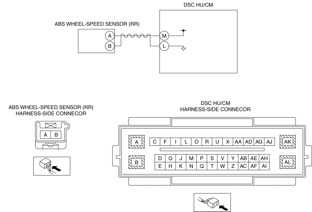
DTC C003A:01/C003A:11/C003A:12/C003A:14/C003A:28/C003A:64 [DSC HU/CM]
| DTC |
C003A:01 |
ABS wheel-speed sensor (RR) |
| C003A:11 |
||
| C003A:12 |
||
| C003A:14 |
||
| C003A:28 |
||
| C003A:64 |
||
| DETECTION CONDITION |
|
|
| FAIL-SAFE FUNCTION |
|
|
| POSSIBLE CAUSE |
|
|
Diagnostic Procedure
| Step |
Inspection |
Action |
|
| 1 |
INSPECT ABS WHEEL-SPEED SENSOR (RR) DATA MONITOR
|
Yes |
Go to Step5. |
| No |
Go to the next step. |
||
| 2 |
INSPECT ABS WHEEL-SPEED SENSOR (RR) SIGNAL CIRCUIT FOR SHORT TO POWER CIRCUIT
|
Yes |
Go to the next step. |
| No |
Refer to the wiring diagram and verify whether or not there is a common connector between ABS wheel-speed sensor (RR) terminal B and DSC HU/CM terminal L.
Go to Step7. |
||
| 3 |
INSPECT ABS WHEEL-SPEED SENSOR (RR) CIRCUIT FOR SHORT TO GROUND CIRCUIT
|
Yes |
Refer to the wiring diagram and verify whether or not there is a common connector in the followings:
Go to Step7. |
| No |
Go to the next step. |
||
| 4 |
INSPECT ABS WHEEL-SPEED SENSOR (RR) CIRCUIT FOR OPEN CIRCUIT
|
Yes |
Go to the next step. |
| No |
Refer to the wiring diagram and verify whether or not there is a common connector in the followings:
Go to Step7. |
||
| 5 |
VISUALLY INSPECT ABS SENSOR ROTOR (RR)
|
Yes |
Go to the next step. |
| No |
Replace the ABS sensor rotor (RR), then go to Step7. |
||
| 6 |
INSPECT CLEARANCE BETWEEN ABS SENSOR ROTOR (RR) AND ABS WHEEL-SPEED SENSOR (RR)
|
Yes |
Go to the next step. |
| No |
Replace the malfunction part, then go to the next step. |
||
| 7 |
VERIFY DTC TROUBLESHOOTING COMPLETED
|
Yes |
Repeat the inspection from Step1. If the malfunction recurs, replace the DSC HU/CM, then go to the next step. |
| No |
Go to the next step. |
||
| 8 |
VERIFY NO DTC IS PRESENT
|
Yes |
Go to the applicable DTC inspection. (See DTC TABLE [DSC HU/CM].) |
| No |
DTC troubleshooting completed. |
||
