< Previous
Next >
PARKING BRAKE LEVER REMOVAL/INSTALLATION
1. Disconnect the negative battery cable. (See NEGATIVE BATTERY CABLE DISCONNECTION/CONNECTION.)
2. Remove the following parts:a. Selector lever knob (with AT vehicles) (See AUTOMATIC TRANSMISSION SHIFT MECHANISM REMOVAL/INSTALLATION.)b. Shift lever knob (with MT vehicles) (See TRANSMISSION REMOVAL/INSTALLATION [M66M-D].)c. Shift panel component (See SHIFT PANEL REMOVAL/INSTALLATION.)d. Upper panel (See UPPER PANEL REMOVAL/INSTALLATION.)e. Parking brake lever boot panel (See PARKING BRAKE LEVER BOOT PANEL REMOVAL/INSTALLATION.)f. Rear console (See REAR CONSOLE REMOVAL/INSTALLATION.)
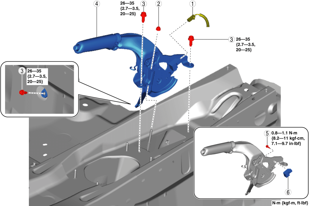
3. Remove in the order indicated in the table.
4. Install in the reverse order of removal.
5. After installation, inspect the parking brake lever stroke. (See PARKING BRAKE LEVER INSPECTION.)
| 1 |
Parking brake switch connector |
| 2 |
Adjusting nut |
| 3 |
Bolt (See Bolt Installation Note.) |
| 4 |
Parking brake lever |
| 5 |
Bolt |
| 6 |
Parking brake switch |
Bolt Installation Note
1. Tighten the bolt A to the specified torque.Tightening torque
26—35 N·m {2.7—3.5 kgf·m, 20—25 ft·lbf}
2. Tighten the bolt B to the specified torque.< Previous Next >Tightening torque
26—35 N·m {2.7—3.5 kgf·m, 20—25 ft·lbf}

