STEERING GEAR AND LINKAGE ASSEMBLY
CAUTION:
To prevent damage to the steering gear, secure it to the vise using a copper plate or clean cloth.
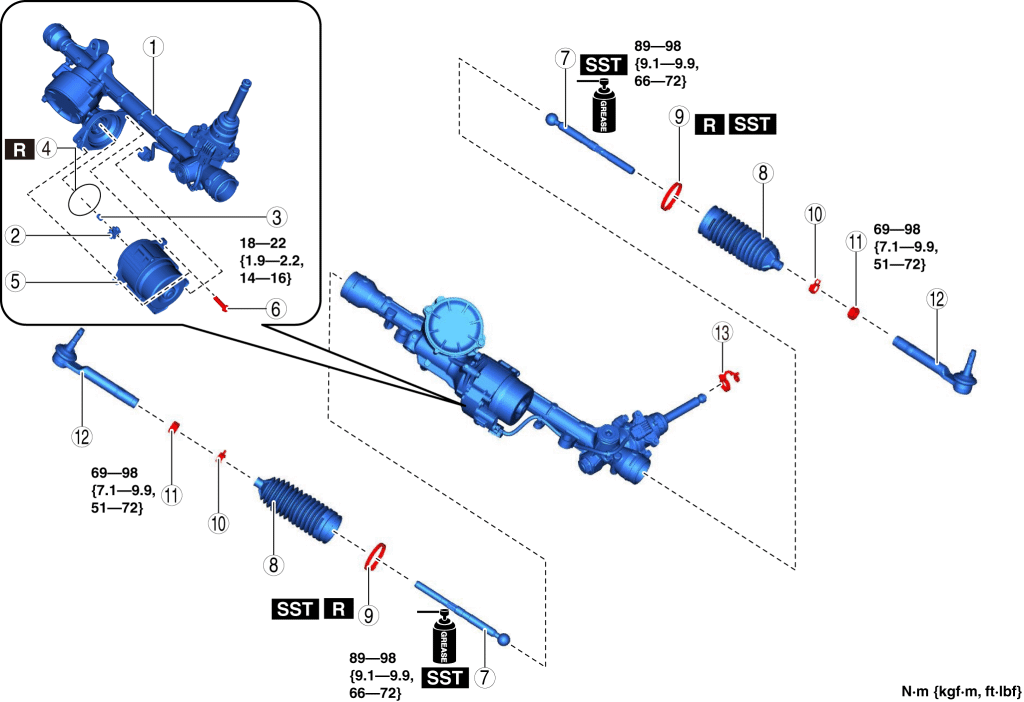
1. Assemble in the order shown in the figure.
2. Install the steering gear and linkage. (See STEERING GEAR AND LINKAGE REMOVAL/INSTALLATION.)
| 1 |
Steering gear |
| 2 |
Rubber |
| 3 |
Spacer |
| 4 |
O-ring |
| 5 |
EPS CM |
| 6 |
Bolt |
| 7 |
Tie rod (See Tie Rod Assembly Note .) |
| 8 |
Boot |
| 9 |
Boot band (See Boot Band Assembly Note.) |
| 10 |
Boot clamp |
| 11 |
Locknut |
| 12 |
Tie-rod end (See Tie-rod End Assembly Note.) |
| 13 |
Clip |
Rubber, Spacer and EPS CM Assembly Note
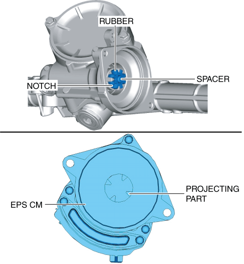
1. Install the rubber and spacer to the steering gear.
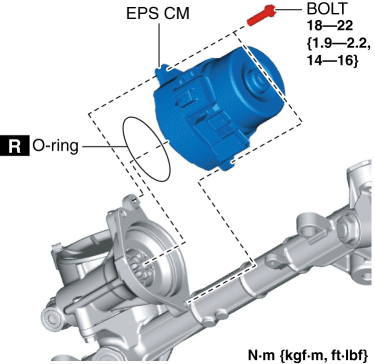
2. Install the EPS CM so that the projecting part of the EPS CM (rotor) is engaged with the notch in the rubber.NOTE:
If the projecting part of the EPS CM (rotor) is not engaged with the notch in the rubber, adjust the position of the EPS CM projection (rotor).
3. Tighten the bolts evenly.
Tie Rod Assembly Note
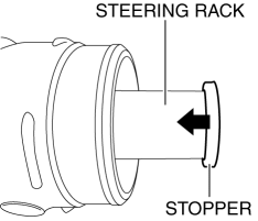
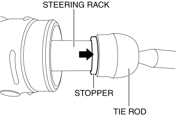
1. If the stopper is placed at the steering rack end, move the stopper in the direction of the arrow so that a wrench can be hooked to the steering rack end.
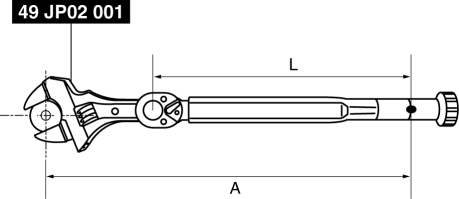
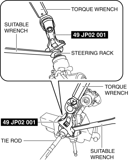
2. Install the SST to the torque wrench as shown in the figure, set it on the tie rod, and measure dimensions A and L shown in the figure.
3. Tighten the tie rod after calculating the tightening torque using the following formula.Tightening torque
89???98 N·m {9.1???9.9 kgf·m, 66???72 ft·lbf}
Calculation formula
T×(L/A)
T:Tightening torque (89???98 N·m {9.1???9.9 kgf·m, 66???72 ft·lbf})
L:Torque wrench effective length
A:Length from center of tie rod to grip
4. Move the stopper at the steering rack to the tie rod end.
Boot Band Assembly Note
1. Assemble the boot band to the boot.
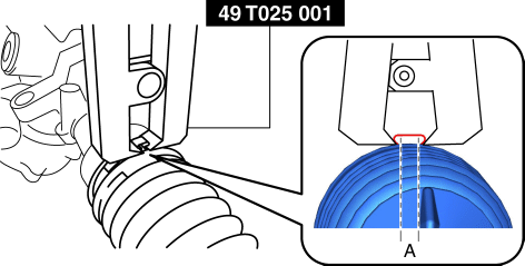
2. Crimp the boot band using the SST.
3. Verify that the crimping clearance A is within the specification.Specification
2.0???3.0 mm {0.08???0.11 in}
If crimping clearance A exceeds the specification, reduce SST clearance, and crimp the boot band again.
If crimping clearance A is less than the specification, increase SST clearance, and crimp a new boot band.
4. Rotate the by hand and verify that it is securely installed to the boot band.
Tie-rod End Assembly Note
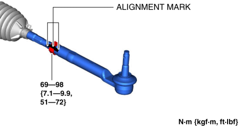
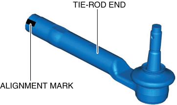
1. Align the marks that were made before removing the tie-rod end, and assemble the tie-rod end to the tie rod.NOTE:
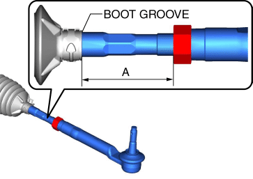
2. Verify that dimension A shown in the figure is within the specification.< Previous Next >Specification
49.8???63.8 mm {1.97???2.51 in} (difference between left and right: 3 mm {0.1 in} or less)
If not within the specification, make adjustments so that dimension A is within the specification.
