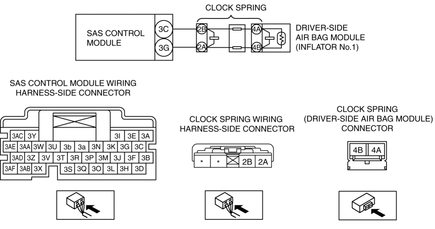
DTC B0001:11/B0001:12/B0001:13/B0001:19/B0001:1A [SAS CONTROL MODULE (TWO-STEP DEPLOYMENT CONTROL SYSTEM)]
| System malfunction location |
|
| Detection condition |
WARNING:
|
| Fail-safe function |
Not applicable |
| Possible cause |
|
Diagnostic Procedure
| Step |
Inspection |
Action |
|
| 1 |
INSPECT DRIVER-SIDE AIR BAG MODULE (INFLATOR NO.1) CONNECTOR WARNING:
|
Yes |
Replace clock spring. (See CLOCK SPRING REMOVAL/INSTALLATION [TWO-STEP DEPLOYMENT CONTROL SYSTEM].) Then go to Step 7. |
| No |
Go to the next step. |
||
| 2 |
INSPECT CLOCK SPRING
NOTE:
|
Yes |
Go to the next step. |
| No |
Replace clock spring. (See CLOCK SPRING REMOVAL/INSTALLATION [TWO-STEP DEPLOYMENT CONTROL SYSTEM].) Then go to Step 7. |
||
| 3 |
INSPECT DRIVER-SIDE AIR BAG MODULE (INFLATOR NO.1) CIRCUIT FOR SHORT TO GROUND
NOTE:
|
Yes |
Refer to the wiring diagram and verify whether or not there is a common connector between SAS control module terminal and clock spring terminal.
Go to Step 7. |
| No |
Go to the next step. |
||
| 4 |
INSPECT DRIVER-SIDE AIR BAG MODULE (INFLATOR NO.1) CIRCUIT FOR OPEN CIRCUIT
NOTE:
|
Yes |
Go to the next step. |
| No |
Refer to the wiring diagram and verify whether or not there is a common connector between SAS control module terminal and clock spring terminal.
Go to Step 7. |
||
| 5 |
INSPECT DRIVER-SIDE AIR BAG MODULE (INFLATOR NO.1) CIRCUIT FOR SHORT TO POWER SUPPLY
NOTE:
|
Yes |
Go to the next step. |
| No |
Refer to the wiring diagram and verify whether or not there is a common connector between SAS control module terminal and clock spring terminal.
Go to Step 7. |
||
| 6 |
INSPECT DRIVER-SIDE AIR BAG MODULE (INFLATOR NO.1)
|
Yes |
Go to the next step. |
| No |
Replace the driver-side air bag module (inflator no.1). (See DRIVER-SIDE AIR BAG MODULE REMOVAL [TWO-STEP DEPLOYMENT CONTROL SYSTEM].) (See DRIVER-SIDE AIR BAG MODULE INSTALLATION [TWO-STEP DEPLOYMENT CONTROL SYSTEM].) Then go to the next step. |
||
| 7 |
PERFORM SAS CONTROL MODULE DTC INSPECTION
|
Yes |
Repeat the inspection from Step 1.
|
| No |
DTC troubleshooting completed. |
||
