DTC P144A:00 [PCM (SKYACTIV-G 2.0)]
NOTE:
To determine the malfunctioning part, proceed with the diagnostics from "Function Inspection Using M-MDS".
Details On DTCs
| DESCRIPTION |
Evaporator system: clogging between fuel tank and fuel tank pressure sensor |
|
| DETECTION CONDITION |
Determination conditions |
|
| Preconditions |
|
|
| Malfunction determination period |
|
|
| Drive cycle |
|
|
| Self test type |
|
|
| Sensor used |
|
|
| FAIL-SAFE FUNCTION |
|
|
| VEHICLE STATUS WHEN DTCs ARE OUTPUT |
|
|
| POSSIBLE CAUSE |
|
|
System Wiring Diagram
Not applicable
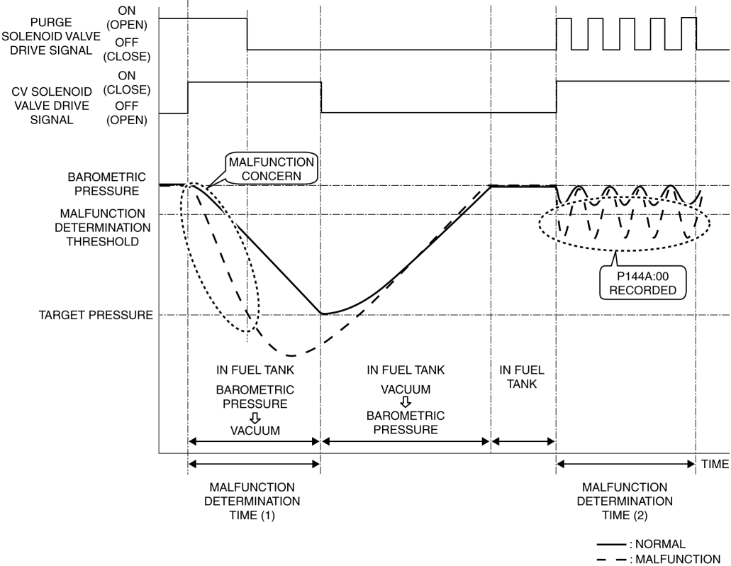
Function Explanation (DTC Detection Outline)
The PCM closes the purge solenoid valve and CV solenoid valve while the vehicle is being driven and seals the fuel tank. Then, gas in the fuel tank is inducted into the intake manifold and the pressure in the fuel tank is decreased by opening the purge solenoid valve, and the pressure change in the fuel tank is measured using the fuel tank pressure sensor. If the pressure in the fuel tank decreases below the target negative pressure during the specified period from the pressure measurement (malfunction determination time (1)), positive pressure is inducted to the fuel tank via the intake manifold by closing the purge solenoid valve and opening the CV solenoid valve. After positive pressure is inducted to the fuel tank, the fuel tank is sealed, opening/closing of the purge solenoid valve is performed repeatedly, and the pressure change in the fuel tank is monitored at that time (malfunction determination time (2)). If the amount of pressure change veers towards negative pressure exceeding the malfunction determination threshold, the PCM determines that there is clogging between the fuel tank pressure sensor and fuel tank, and stores a DTC.
Repeatability Verification Procedure
Set the remaining fuel quantity in the fuel tank between 30—85 %.
Verify that OBD-II information (such as FREEZE FRAME DATA) has been obtained and recorded.
Clear the DTC from the PCM memory using the M-MDS. (See CLEARING DTC [PCM (SKYACTIV-G 2.0)].)
Start the engine and switch the ignition off after 5 s have elapsed.
Leave the vehicle for 6 hours or more.
Start the engine and leave it idling for 2 min.
Drive the vehicle for 30 min at a speed of 50 km/h {31 mph} or more (to increase temperature in fuel tank and generate evaporative gas).
NOTE:
If driving the vehicle for 30 min at a speed of 50 km/h {31 mph} or more is not feasible, the vehicle can be driven for a continuous 15 min or more with the engine coolant temperature at 80 °C {176 °F} or more.
Stop the engine.
Leave the vehicle for 1 hours or more.
PID Item/Simulation Item Used In Diagnosis
PID/DATA monitor item table| Item |
Definition |
Unit |
Condition/Specification |
| FTP |
Fuel tank pressure |
KPa , mBar , psi, in H20 |
|
| Fuel tank pressure sensor voltage |
V |
|
| Item |
Definition |
Unit |
Operation |
| EVAPCP |
Purge solenoid valve control signal |
% |
|
| EVAPCV |
CV solenoid valve control signal |
Off/On |
|
Function Inspection Using M-MDS
| STEP |
INSPECTION |
RESULTS |
ACTION |
| 1 |
PURPOSE: VERIFY RELATED REPAIR INFORMATION AVAILABILITY
|
Yes |
Perform repair or diagnosis according to the available repair information.
|
| No |
Go to the next step. |
||
| 2 |
PURPOSE: RECORD FREEZE FRAME DATA/SNAPSHOT DATA AND DIAGNOSTIC MONITORING TEST RESULTS TO UTILIZE WITH REPEATABILITY VERIFICATION NOTE:
|
— |
Go to the next step. |
| 3 |
PURPOSE: VERIFY IF FUEL GAUGE SENDER UNIT HAS MALFUNCTION
|
Yes |
Perform the DTC troubleshooting for the fuel gauge sender unit first because the fuel gauge sender unit cannot detect the fuel tank level and determines that a malfunction is occurring. (See DTC P0460:00 [PCM (SKYACTIV-G 2.0)].) (See DTC P0461:00 [PCM (SKYACTIV-G 2.0)].) |
| No |
Go to the next step. |
||
| 4 |
PURPOSE: VERIFY FUEL TANK PRESSURE SENSOR MEASURED CORRECTLY
|
Yes |
The fuel tank pressure sensor measures correctly.
|
| No |
The possibility of a fuel tank pressure sensor malfunction is high.
|
||
| 5 |
PURPOSE: VERIFY IF PURGE SOLENOID VALVE IS STUCK OPEN
|
Yes |
The possibility of a stuck purge solenoid valve open is high.
|
| No |
The possibility of clogging between fuel tank pressure sensor and fuel tank is high.
|
Troubleshooting Diagnostic Procedure
Intention of troubleshooting procedure
Step 1
Perform a PCM input signal part-related inspection.
Step 2
Perform a unit inspection of the purge solenoid valve.
Step 3—6
Inspect for clogging between fuel tank pressure sensor and fuel tank.
Step 7—8
Verify that the primary malfunction is resolved and there are no other malfunctions.
| STEP |
INSPECTION |
RESULTS |
ACTION |
| 1 |
PURPOSE: DETERMINE INTEGRITY OF FUEL TANK PRESSURE SENSOR
|
Yes |
Replace the charcoal canister, then go to Step 7. (See CHARCOAL CANISTER REMOVAL/INSTALLATION [SKYACTIV-G 2.0].) |
| No |
Go to the next step. |
||
| 2 |
PURPOSE: DETERMINE INTEGRITY OF PURGE SOLENOID VALVE
|
Yes |
Replace the purge solenoid valve, then go to Step 7. (See PURGE SOLENOID VALVE REMOVAL/INSTALLATION [SKYACTIV-G 2.0].) |
| No |
Go to the next step. |
||
| 3 |
PURPOSE: VERIFY IF THERE IS CLOGGING BETWEEN FUEL TANK PRESSURE SENSOR AND FUEL TANK
|
Yes |
Repair or replace the malfunctioning part according to the inspection results, then go to Step 7. |
| No |
Go to the next step. |
||
| 4 |
PURPOSE: DETERMINE INTEGRITY OF PRESSURE CONTROL VALVE
|
Yes |
Replace the pressure control valve, then go to Step 7. |
| No |
Go to the next step. |
||
| 5 |
PURPOSE: DETERMINE INTEGRITY OF FUEL SHUT-OFF VALVE
|
Yes |
Replace the fuel tank, then go to Step 7. |
| No |
Go to the next step. |
||
| 6 |
PURPOSE: DETERMINE INTEGRITY OF ROLLOVER VALVE
|
Yes |
Replace the fuel tank, then go to the next step. |
| No |
Go to the next step. |
||
| 7 |
PURPOSE: VERIFICATION OF VEHICLE REPAIR COMPLETION
|
Yes |
Repeat the inspection from Step 1 of the troubleshooting diagnostic procedure.
Go to the next step. |
| No |
Go to the next step. |
||
| 8 |
PURPOSE: VERIFY IF THERE IS ANY OTHER MALFUNCTION
|
Yes |
Go to the applicable DTC inspection. |
| No |
DTC troubleshooting completed. |